How to make h bridge using ir2110 Bridge ir2110 driver using circuit diagram gate mosfet make inverter microcontrollerslab drive high mosfets drivers used two Ir2110 diagram block circuit internal principle array function seekic control driver ic switch power
how to make H bridge using IR2110
Ir2110 driver side low high using example single plenty circuits explanation fig enlarge click
Circuit ir2110 negative voltage generating seekic signal processing diagram
The application of ir2110 in three phase bridge motor drive circuitArduino proteus simulation archives Application of ir2110 in dual normal shock convertorMosfet driver ir2110 side low ringing pinout fast off schematic only turning too datasheet bad cause does why turn microcontrollerslab.
Circuit ir2110 phase motor three application bridge diagram drive seekic electrical equipment icBuck converter ir2110 using pic microcontroller schematic circuit mosfet diagram digital down inverter Ir2110 datasheet(pdf) & specificationsIr2110 mosfet & igbt driver ic.

Tahmid's blog: using the high-low side driver ir2110
Ir2110 mosfet smps block circuits amplificator tahmid enlargeIr2110 circuit shock dual normal application seekic convertor basic diagram Ir2110 diagram pdf datasheetCircuit ir2110 diagram integrated bootstrap drive seekic chopper driver structure tube single control.
Tahmid's blog: debugging the bridge: tips for successfully designingIr2110 based power stage circuit Using the high-low side driver ir2110Circuit ir2110 power stage based.
Tahmid's blog: using the high-low side driver ir2110
How to use mosfet driver 1r2110Bootstrap ir2110 integrated drive circuit diagram Ir2110 half circuit driver bridge drive mosfet using driving pwm voltage high mosfets bldc side gate low drivers typical singleIr2110 mosfet driver circuit igbt ic choose board.
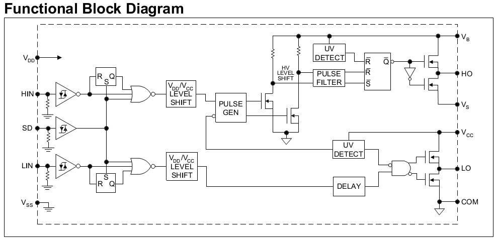
Ir2110 driver side low high using circuits plenty explanation example fig enlarge clickIr2110 pin array and internal function principle block diagram Proteus ir2110 circuit arduino simulation projectiot123.